PERFORMANCE STANDARDS
By: John W. Davis, PE
During the past several months, I have participated in a number of court cases which are worth reviewing for purposes of improved risk management. I assume it’s no revelation to you that each time you certify a crane, you assume a certain amount of risk. The trick is to minimize that risk. You may not be doing the things noted below, but you can use these comments to firm up your resolve to strengthen your risk management situation.
A recent case in California involved a commercial truck mounted crane that dropped a suspended load because the winch brake slipped and a worker was crushed. The crane had been inspected within the previous two months by a certifier and the brake problem had not been discovered. Other deficiencies had been discovered and listed and they were repaired by a service facility. Some of the repairs were structural and it was undetermined whether or not the crane had been load tested. In any event, the brake problem remained unidentified. The crane was returned to the owner and a couple of days later the injury occurred. The court found that the responsibility rested on the certifier because he failed to inspect or test the brake. His insurance settled for the limits of his policy. This case demonstrates the wisdom of testing at rated line pull and/or checking brake adjustment and wear. Failure of the certifier to determine that hoist brakes are within operational specifications is not defensible, even if a repair facility has worked on the crane in the repair-verification-certification process.
In another case an iron worker was killed when the power down brake failed to hold, dropped the load, and crushed him. The brake had not been inspected for several years nor had the function been tested at maximum line pull. The certifier and the owner were both held responsible because both had failed to heed the manufacturer’s instruction to inspect the brake at specific periods and the certifier had failed to test it. This case also demonstrates the wisdom of testing the hoist at rated line pull at minimum. Trial attorneys have the nasty habit of attacking if we inspect and don’t test or test and don’t inspect! The only sure way to minimize the risk is to do both. This issue is not limited to hoist brakes. The same concerns exist with boom elevation capacity and auxiliary hoists. Line pull capacities and boom elevation capability don’t require much weight to test and it seems foolish to leave it undone and risk a devastating law suit.
Another problem has surfaced regarding conventional crane booms. In this case, the 180-foot boom with a 60-foot jib failed and killed a laborer who was eating his lunch. It was determined that boom sections had been inspected prior to erection, but the specific section that failed was not specifically identified so the inspection was challenged and the owner’s insurance paid. I suggest that it is particularly important to identify the boom sections so that your inspection and load test can be substantiated.
Some manufacturers serialize the boom sections. If they don’t, the certifier should stamp an appropriate identification on each section and record the section identifications on the load test documents. I still notice that, from time to time, single pick quadrennial tests are being done. There’s no way this practice can be defended. Also, I notice frequent load tests that don’t even approach 50% of maximum capacity, which is hard to defend. Additionally, if the load tests are not designed to impose maximum line pull on multi-part reeving as well as on single line hoists, the load test is not really defensible. Take a look at CCAA Load Test Procedure for guidance on load testing.
Remember, by the time the attorneys look at an accident, the only thing left is the paper record and the fragile memories of percipient witnesses. Be sure that your certificates and check lists display sufficient information to demonstrate compliance with the regulations of appropriate jurisdiction. If they don’t look good to me, an attorney will attack them relentlessly; it only takes once!
Document is shared with the kind permission of John Davis, a colleague and fellow director at the Crane Certification Association of America (CCAA). The association promotes crane safety, improvement of the certification profession and addresses the subject of crane safety in governmental forums.
For more information visit the association page: http://ccaaweb.net/associations/1297/CCAANL0910.pdf
www.waterweightsinc.com
Thursday, December 16, 2010
Wednesday, December 15, 2010
Structural Verification and Deck-Platform Testing

The Water Weights range of flexidams and mattress bags allows uniform surface loadings to be applied. Advantages over traditional solid weights include ease of handling and positioning on site, very low carriage costs and gradual application of load (often over a period of several days).
Loading is measured by means of a calibrated flowmeter to give accuracy of +1/-2%. By using our simple manifold arrangement several units can be filled simultaneously.
Water Weights provides specialist products, services and project management for structural testing. This includes verification of structural integrity of buildings, testing of bridges, elevators, loading ramps, gangways and decks.
Specific examples of applications include:
Roll on, roll off ferry ramps have been tested ranging from 70 to 600 tonnes
Ballasting arrangements for ship's conversion up to 300 tonnes
General floor testing applications to verify structural integrity on renovation; change of use or suspected structural damage. Examples include, 130 tonnes to an educational establishment and 40 tonnes to an historical monument.
Passenger and freight elevator testing.
For further information visit:
http://www.waterweightsinc.com/en/deck-loading-testing.html
Monday, December 6, 2010
WATER WEIGHTS for testing Aircraft Elevators
Internal Study for US Navy Fleet Benefits

Aircraft Elevators are designed primarily to transport aircraft between the hangar deck and the flight deck. They are, however, also used to transport cargo and equipment. Aircraft Elevators are found on aircraft carriers and on some amphibious assault ships such as LHA’s, LPH’s and LHD’s. All aircraft elevators use hydraulic engines, sheaves, and wire ropes to lift and lower the Platform.
There are two major types of aircraft elevators, the deck edge and the inboard types. These names refer to the location of the elevator platform on the ship. The machinery for inboard and deck edge elevators operates under the same principles and is similar in arrangement. Deck edge elevators are cantilevered off the hull of the ship. Inboard elevators use the platform as a hatch at the flight deck.
Guide rails and rollers constrain the platform so it can only move in the vertical position. Mechanical Locks hold the platform in place at the flight deck level taking the load off the wire rope.
Elevator Testing
New and modified aircraft elevators are tested prior to regular operation to ensure proper performance of all elevator components. There are no periodically required tests of aircraft elevators. However, because load testing and operational testing are required whenever hoisting wire ropes are replaced, every aircraft elevator will be tested at least once every five (5) years.
Load testing proves the ability of an elevator to perform properly through the complete range of operating limits with the platform loaded. The aircraft elevator require load testing with the rated load only. The stress applied by ship motion on the load bearing components is less than the stress due to normal operation.
The operational characteristics of the aircraft elevator require that additional loading effects of ship motion on the platform and its rated load at the flight deck level will not stretch the wire ropes and cause the platform to drop below the deck level. The flight deck is held tight to the flight deck because the hydraulic engine applies a load to the wire ropes beyond that which would be added by ship motion. The loading is applied every time the platform reaches the flight deck, regardless of weight on the platform. Hence, A static and dynamic load test (typically 150-200%) over the rated load capacity would not provide any additional assurance of proper elevator operation.
According to the Naval Ships’ Technical Manual (Chapter 588) an aircraft elevator must be fully load tested after repair or replacement of any of the following components:
1.Wire ropes
2.Sheaves and cross head
3.Hydraulic Engine (ram or cylinder)
4.Guide rails
5.Platform structure
6.Guide or face rollers
Traditional Method.
Labor and support equipment using current methods with steel or concrete weights with an average test time of 5 days for all elevators. Assumption is that the testing is done as part of a shipyard contract.
1.Support crane on pier (for testing inboard elevators)
2.YTD crane (for testing outboard waterside elevators) or Support crane lifted onboard the flight deck in order to reach waterside elevators.
3.Tug for positioning YTD crane or rental of barge mounted crane
4.Crane Operator
5.Minimum of 5 Riggers for positioning weights
6.Test Director
7.Electrician
Water Weights Method
Using the Water Weights method, all testing would be completed in two days. No dockside crane support is required. Two technicians complete all labor requirements. All equipment is transported in a pick-up truck.
Equipment used was as follows: -
8 x 8 tonne (17632 lbs) WATERWEIGHTS test bags
4 x Certified Flow Meters
1 x Manifold Filling Assembly
3 x 50ft Fire Hoses
2 x Diaphragm Pumps (used for emptying the bags)
Fill time (assuming 240 gallons per minute) to achieve full load is 40 minutes. Emptying (using diaphragm pumps) is approximately 30 minutes.
Given the figures above the obvious cost savings is huge compared to traditional methods. Additionally, testing takes 48 hours as opposed to 5 days. This might allow a shortening of the time the ship spends in dock, and therefore increased availability. Finally, two other important issues may have significant effect.
A)The above estimates assume that all elevators will be tested one after the other on the same mobilization. This rarely happens. The additional costs of separate mobilizations of tugs, YTD and shore based cranes dramatically widens the cost differential between the WATER WEIGHTS method and traditional methods.
B)Inevitably there are failures and the need for re-test. The cost of mobilization for re-test using WATER WEIGHTS will be lower.
C)There is also the added benefit of scheduling flexibility to both the testing activity and the ship itself because of the elimination of trying to schedule a support crane, tug or crane barge on scheduled test days.

Friday, November 12, 2010
Innovative Way of Testing Underway Replenishment Systems Using Water Weights

The common methodology adopted to test the Underway Replenishment (UNREP) equipment aboard ship is to utilize a dockside or floating crane, a set of test weights and a preventer line to control the angle of the test loads applied, and to ensure that the suspended weights from the crane are kept truly vertical so as not to overload the crane.
The preventer line has to be attached to a strong point on the wharf or floating crane barge, and has the potential to cause a mishandled crane to be overloaded and damage the jib or slewing ring. The test equipment and rigging also has to take into account the height difference between the deck level, test points, availability of strong points for fixing the preventer lines and availability of a suitable crane able to support the full test weight. This methodology is traditionally time consuming and expensive.
All of these problems can be overcome by the use of a gin pole acting as a strut to convert the water Weights into the required pull on the UNREP pad-eye or sliding block. Altering the length of the gin pole would facilitate testing angles in the vertical plane and fixed rigging points on the vessel with adjustable rigging wires would permit the tests to be conducted at a variety of angles fore and aft of a beam, all with the minimum of difficulty.
In addition, the use of a gin-pole would preclude the necessity for a crane to support the test weight other than for rigging the test. This removes the likelihood of shock loading the crane from the impulse of a dropped load should the item of equipment being tested fail. The use of water bags will allow the gradual application of load, together with monitoring key components of the system during the test, thus ensuring that UNREP testing does not create a hazardous situation.
System Description
• Adjustable length gin pole and Water Weights bag
• Load attachment plate
• Base plate and deck load spreader
• Lateral restraint rigging
The gin pole is erected with its rigging to fixed points on the ship such that the gin pole acts to strut the test load off the vessel and convert the vertical test load to a horizontal pull. The UNREP testing can then be carried out very simply by adjusting the length of the gin pole with the addition of intermediate sections to achieve the ±30º vertical alignment about mid-position and by adjusting the lateral restraint rigging to alter the fore and aft alignment of the test.
The use of a gin pole allows the resolution and transfer of the test loads into the internal structure of the vessel by the base plate and deck load spreader without the need for a preventer line to a dock side fitting or bollard. Load monitoring and measurement can be integrated with the gin pole and rigging to ensure the specified test loads are being applied to the UNREP system to meet the design intent.
Water Weights also has the ability to provide a full monitoring suite of instrumentation during testing to determine the ongoing structural integrity of the UNREP system. Typical techniques include the use of Acoustic Emission fingerprinting and monitoring during load applications, instrumented load pins in the primary load paths, rotary encoders for accurate measurement of line angles and telemetry load links able to remotely report the loading regime under which the test is being carried out.
Note: The company is in the process of fitting a full set of monitoring equipment to a Royal Navy Type 23 frigate to monitor the actual loads in real time experienced by the Replenishment At Sea (RAS) system during a period of sustained use under a variety of sea states, load transfers, connected platforms and operational environments. This is part of a data gathering exercise to support the development of a higher load capacity and throughput RAS system for the Royal Navy future carrier project.
For more info visit: http://www.waterweightsinc.com/files/files/US_Downloads/UNREP_Testing.pdf
Monday, November 1, 2010
From the pages of OSHA; Cranes and Derricks in Construction Final Rule

The U.S. Department of Labor's Occupational Safety and Health Administration (OSHA) released a historic new standard, addressing the use of cranes and derricks in construction and replacing a decades old standard. The significant number of fatalities associated with the use of cranes and derricks in construction and the considerable technological advances in equipment since the publication of the old rule, issued in 1971, led the Labor Department to undertake this rulemaking.
In 1998, OSHA's expert Advisory Committee on Construction Safety and Health (ACCSH) established a workgroup to develop recommended changes to the current standard for cranes and derricks. In December 1999, ACCSH recommended that the Agency use negotiated rulemaking to develop the rule. The Cranes and Derricks Negotiated Rulemaking Committee (C-DAC) was convened in July 2003 and reached consensus on its draft document in July 2004. In 2006, ACCSH recommended that OSHA use the C-DAC consensus document as a basis for OSHA's proposed rule, which was published in 2008. Public hearings were held in March 2009, and the public comment period on those proceedings closed in June 2009.
* The rule becomes effective 90 days after August 9, 2010, the date the final rule was published in the Federal Register. Certain provisions have delayed effective dates ranging from 1 to 4 years.
* The final rule was published on August 9, 2010 by the Federal Register, and can be found at http://www.osha.gov/FedReg_osha_pdf/FED20100809.pdf.
* A copy of the regulatory text is available at: http://www.osha.gov/doc/cranesreg.pdf
* This new standard will comprehensively address key hazards related to cranes and derricks on construction worksites, including the four main causes of worker death and injury: electrocution, crushed by parts of the equipment, struck-by the equipment/load, and falls.
* Significant requirements in this new rule include: a pre-erection inspection of tower crane parts; use of synthetic slings in accordance with the manufacturer's instructions during assembly/disassembly work; assessment of ground conditions; qualification or certification of crane operators; and procedures for working in the vicinity of power lines.
* This final standard is expected to prevent 22 fatalities and 175 non-fatal injuries each year.
* Several provisions have been modified from the proposed rule. For example:
o Employers must comply with local and state operator licensing requirements which meet the minimum criteria specified in § 1926.1427.
o Employers must pay for certification or qualification of their currently uncertified or unqualified operators.
o Written certification tests may be administered in any language understood by the operator candidate.
o When employers with employees qualified for power transmission and distribution are working in accordance with the power transmission and distribution standard (§ 1910.269), that employer will be considered in compliance with this final rule's requirements for working around power lines.
o Employers must use a qualified rigger for rigging operations during assembly/disassembly.
o Employers must perform a pre-erection inspection of tower cranes.
* This final rule requires operators of most types of cranes to be qualified or certified under one of the options set forth in § 1926.1427. Employers have up to 4 years to ensure that their operators are qualified or certified, unless they are operating in a state or city that has operator requirements.
* If a city or state has its own licensing or certification program, OSHA mandates compliance with that city or state's requirements only if they meet the minimum criteria set forth in this rule at § 1926.1427.
* The certification requirements in the final rule are designed to work in conjunction with state and local laws.
* This final rule clarifies that employers must pay for all training required by the final rule and for certification of equipment operators employed as of the effective date of the rule
* State Plans must issue job safety and health standards that are “at least as effective as” comparable federal standards within 6 months of federal issuance. State Plans also have the option to promulgate more stringent standards or standards covering hazards not addressed by federal standards.
* OSHA will have additional compliance assistance material available within the next month.
July 28, 2010
http://www.osha.gov/as/opa/cranesderricks-factsheet.html
Thursday, October 28, 2010
About Proportional Load Measurement Systems

The majority of load measurement systems are used on cranes having multiple rope falls where the load seen by the hook is shared proportionally between the numbers of ropes used in the rigging. On most of these applications, the load measurement transducer is positioned at some point in the rigging, (the rope tie-off point or the compensation sheave or the compensation lever) where only a proportion of the load is measured by the instrument (load pin, load link, wedge socket, clamp-on, etc.).
The dilemma faced with these type systems is the repeatability and accuracy of the load measured compared with that seen at the hook. When only a proportion of the load is measured by the transducer, any losses in the crane rigging systems due to friction in sheave bearings and friction in ropes traveling around the sheave radius is amplified through the load measurement system by the number of times the transducer load is multiplied to equal the crane capacity (parts of line).
Consider this example; An overhead bridge crane with a lifting capacity of 500 tons utilizing 20 ropes in rigging, with each rope (theoretically) taking 25 tons or 5% of the entire load. If a load transducer is placed in the compensation sheave
where the load from two ropes is supported, the output from the transducer is amplified by 10 times to enable the display to show 500 tons. Any losses in the rigging sheaves, both at the point of loading and during lifting and lowering of the load are also amplified 10 times. Therefore, a loss in sensing the load of 1%, between the hook and the point where the transducer is installed, is amplified to 10% on the display.
The error potential is even greater with clamp-on transducers and line riders in multiple rope cranes. These devices can only measure a percentage of the load seen through the deflection in the rope. Accuracy and repeatability is frequently quoted at plus or minus 5% to begin with, add on the issue of friction losses in the
rigging and you can see the limitations in accuracy and repeatability.
What can be done? Consider installing additional load measurement transducers in the rigging so that a higher percentage of the load is measured by the system, or ask us about our load measuring systems mounted on the hook block.
http://www.waterweightsinc.com/en/crane-load-measuring-monitoring.html
Tuesday, October 26, 2010
Testing Lifeboats Using Water Weights
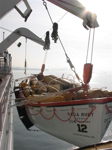
Water Weights lifeboat proof load testing systems have been specifically designed to meet regulatory requirements for an evenly distributed load. Our remote system allows Proof Load Testing to be conducted safely, without the need for personnel to enter the craft during the proof loaded condition.
Water Weights lifeboat bags allow ease of handling and transportation compared with solid weights or traditional sand bags, especially in totally enclosed lifeboats.
Controlled loading, unloading and minimal handling of the test load to achieve a wide range of capacities, results in minimum downtime of equipment during test. Loading is measured by means of a calibrated flowmeter.
Remote System
A control manifold and pumping system are used to remotely fill the lifeboat bags negating the need for personnel to be in the craft during test. This system also remotely removes the test overload in instances where the winching system cannot recover the craft in its proof load condition. The bags are rated +/-1% of load when filled. Gradual application of load under test conditions is essential. This is more easily achieved using Water Weights than traditional solid weights.
Safety of Life at Sea (SOLAS)
SOLAS requirements Chapter III, for life saving appliances, details the testing procedures. Water Weights bags also comply fully with the Maritime and Coastguard Agency (MCA) regulations and US Coastguard requirements.


Thursday, October 21, 2010
Load Measuring Systems Installed in the Crane Hook Block

For users with requirements to measure and display the load accurately at the hook, adopting the use of dynos (load links and shackles) which are suspended beneath the hook becomes the easiest standard. These devices provide significantly more accurate and repeatable load readings in comparison to the integrated proportional load measurement system. The load is transferred directly to them, via minimum rigging, ensuring minimal losses.
For clients that require a permanently installed solution, then a custom designed in hook load measurement device is the answer. By placing the transducer within the hook or close to it, we ensure that the load seen at the hook can be transferred almost directly to the transducer measuring the load. The displayed load is not an electronically amplified value and therefore losses are minimized.
A custom designed transducer involves replacing the hook trunnion with an instrumented strain gauged trunnion or installing a precision load measurement transducer within the hook or between the hook and the rope. The latter being suitable for crane of lighter duty with single rope connections, frequently termed “whip hooks”.
When these devices are connected to multi-linearization electronics, the accuracy and repeatability can be tuned to provide accuracies within the 0.1%, or better, of the cranes operating capacity.
For more information, visit:
http://www.waterweightsinc.com/en/load-measurement.html
Monday, October 18, 2010
Water Over the Turbine Generators. Oh My!

The mere thought of hundreds of tons of water hanging over electrical equipment is intimidating enough. But having it over machinery responsible for the power supply of thousands of households and businesses is almost unheard of during the infancy of Water Weights.
Fast forward to the present, the method is now the norm in testing both conventional and nuclear powerhouse cranes across the country. This is a tribute to the safety, design & engineering of equipment, and dedication of all at Water Weights and the crane testing industry.
Besides the obvious advantages of cost effectiveness, time efficiency during mobilization, and handling of the test weights, the important issue of minimal floor loading is a tremendous advantage. Testing with traditional methods in the past (especially in the heavy ranges above 200 tons), required reinforcing turbine deck structures to handle the fully laden solid weights. Gradual application of load under test conditions has also proven essential in avoiding accidents and damage during testing.
Proof load testing is an essential part of any inspection, repair, and maintenance program for lifting equipment. In situations where live load testing is not specifically mandated, it is still an essential element of safe maintenance and protection from liability.
Our proof load testing bags have evolved a long way since the standard bags originally designed for testing in the offshore oil industry. The current systems not only work in the harshest of environments but also are the safest, accurate and most efficient in testing cranes inside plants and onshore sites.
The use of water filled bags for load testing all kinds of lifting equipment is now recognized worldwide as a safe, efficient and cost effective system. With Water Weights you pay for the actual crane test, not the transportation.
For more information please visit:
http://www.waterweightsinc.com/en/utilities.html
Thursday, October 14, 2010
On Proof Load Testing and WaterWeights
1. In majority of countries, load testing of lifting equipment is a mandatory requirement. Such requirements are legal minimums and many companies or industries choose to set more rigorous standards internally.
2. Proof load testing is an essential part of any inspection, repair and maintenance program for lifting equipment. In situations where live load testing is not specifically mandated, it is still an important element of safe maintenance and advisable for liability purposes.
3. A successful proof load test instills confidence in customer, operator and owner of lifting equipment.
4. Use of Water Weights bags for load testing all manner of lifting equipment is recognized world-wide as a safe, efficient and cost effective method.
5. Water Weights bags have been specifically designed and physically proof load tested to verify that their operational integrity exceeds safety standards for lifting equipment.
6. All equipment has a proven and certified factor of safety in excess of 6:1.
7. Gradual application of the load under test conditions is key in achieving a safe and controlled environment during testing. This method identifies any fault or defects in the equipment under test, before catastrophic failure occurs. This is only possible by using Water Weights.
8. In the event of failure of equipment being tested, consequential loss or damage is limited and often prevented using Water Weights.
9. There have been several serious accidents during proof load testing involving substandard water containers which were simply not designed for the physical demands of proof load testing. We strongly advice users to request evidence of "physical proof load test", from a recognized government body or testing authority proving that equipment meets with the minimum factor of safety legally required.
10. All Water Weights bags come fully certified with evidence of physical proof load test, and type test from the American Bureau of Shipping (ABS), and Water Weights is certified to ISO 9001-2008.
For more information, please visit www.waterweightsinc.com
Friday, October 8, 2010
Crane Load Testing and the Environment

At Water Weights we are committed to environmental awareness and preservation. We conduct our activities in a manner that manages environmental issues responsibly.
We fulfill this commitment by:
Lowering the carbon footprint when crane testing compared to traditional methods
Invasive species mitigation and prevention through equipment inspection procedures
Conducting operations in an environmentally sound manner without disturbing local ecosystems during testing
Promoting environmental responsibility among our employees
Pursuing continuous improvement in our environmental performance
Carbon Footprint
Transporting Water Weights water bags to a test site causes considerably less CO2 emissions than using traditional solid weights. The following numbers are based on travel of 100 miles for a 100 ton load test:
Transporting solid weights by road:
Number Semi-tractor trailers needed: 6
Estimated CO2 emissions: 0.9 tons
Transporting solid weights by rail:
Number rail cars needed: 2
Estimated CO2 emissions: 0.3 tons
Transporting Water Weights bags by road:
Number of Water Weights pickup trucks and trailers: 1
Estimated CO2 emissions: 0.08 tons
Aquatic Nuisance Species
Aquatic nuisance species (ANS) (sometimes called exotic, invasive, non-indigenous or non-native) are organisms that invade ecosystems beyond their natural, historic range. Their intentional or unintentional release may harm native ecosystems or commercial, agricultural, or recreational activities dependent on these ecosystems.
Water Weights’ inspection procedures address the challenge of unintentional introduction of ANS into our waterways through crane testing. These procedures are part of internal processes certified to ISO 9001:2008.
Enhancing Crane Load Testing
Traditional crane management in the US is based upon periodic inspection, routine maintenance and (depending on regulation) load testing up to 125% of safe working load.
Periodic inspection tends to limit itself to the externally visible structure and the mechanical components. Proof load testing of cranes gives a snapshot of the asset’s capability at the time of testing and an overview of the general mechanical condition of the asset. It does not give any information with regard to the internal structural integrity of the asset or indeed any future structural verification. Risk based NDE will be used on a very limited basis. Many facility cranes were installed in the 1960’s and are now reaching the end of their design life. This leaves the alternatives of replacement or life extension to support the extended life of the facilities they serve.
Water Weights Inc. works with Imes who approaches the management of cranes in a different way. This approach requires a full understanding of the structural integrity of the asset, the effect of corrosion on the rated capacity, an assessment of fatigue cycle history and a thorough understanding of the remaining life of the asset.
The Imes technology has the capability to establish these parameters for existing cranes and is able to develop a long term management plan to achieve the maximum life from these assets. The capability of the asset is determined by inspection using visual, acoustic and other non-destructive techniques (depending on the particular asset). This is coupled with a corrosion study and the degraded material properties are modeled in a Finite Element package. This model is used to determine the capacity and capability of the asset as it currently is, compare it to its original design code and establish its performance against current design codes. Predictions of performance against the load test can be made and verified by instrumentation mounted on the crane during test. Areas of weakness can be identified and an engineering plan put in place to re-establish the asset integrity before a load test is failed. The ability to predict failure modes with this methodology also enhances the safety argument for maintaining ageing assets in operation
The difference between periodic inspection and testing and condition / reliability based approaches is that, in the latter, the condition of the asset is constantly understood, monitored and managed. Instrumentation is provided on the crane to record load history and other appropriate parameters to the asset. Predictive techniques are employed to support maintenance/replacement on condition instead of period, and life expectancy of the asset can be accurately forecast for budget and capital finance planning.
Water Weights working with Imes are able to offer this service as an enhancement to load testing. In the event where a full load test is not possible for any reason, using this technology without a full proof load or where critical lifts are being made enables the management and mitigation of risk.
Thursday, October 7, 2010
About US

Water Weights provides specialist proof load testing products and services.
Water Weights' water filled proof load bags were originally designed in 1979, as a safer and more cost effective alternative to solid weights, for testing the safe working load of cranes on North Sea oil & gas installations. This simple idea quickly became a revolutionary alternative to traditional methods of testing lifting equipment.
Since those early days, continued product development of what has become a highly engineered and certified system, greatly increased the practicality, economy and safety of providing proof load testing in various industrial applications. In addition, certain proof load testing situations have only become feasible because of Water Weights. Applications have expanded to include all types of cranes, lifting equipment, lifeboats, davits, elevators, platforms and bridges.
The company's continuing evolution enabled expansion of expertise to encompass a wide variety of associated services and engineering project management. Water Weights now provide load measurement systems and services including crane systems, tension load links and shackles, batching systems, bare load cells, installation, calibration, and other specialist load monitoring packages.
Water Weights' customer base now includes oil & gas, defense, construction, process, power & utilities, and marine & shipping industries offering global services in 15 countries in four continents.
Water Weights' core commitment is the provision of products and services to the highest standards. The company is registered to ISO 9001:2008.
Water Weights in Power Generation Plants

Water Weights are extensively used in the testing of cranes in power generation facilities. Water Weights load test bags are light and easy to transport, weighing less than 1.5% of rated load when empty and rolled. The water bags also come ready rigged and ready for placement onto crane hook, which saves on set up, and labor costs.
Controlled loading and minimal handling to achieve a wide variety of loads (% of SWL) equate to minimum downtime for equipment under test. The bags are rigged empty and filled while suspended which eliminates having to reinforce the deck structure when testing with solid weights, especially in the higher ranges.
All Water Weights bags have a designed factor of safety in excess of 6:1 and each bag is physically proof load tested to minimum of twice it's rated capacity. All bags are fully certified and come with documentation of inspection and testing from birth. We fully recommend you ask your supplier for documentation of certification when using any test equipment on critical equipment and facilities.
Water Weights is fully committed to environmental awareness and preservation. We conduct our activities in a manner that manages environmental issues responsibly. Water Weights fully manage environmental impact by:
•Lowering the carbon footprint when crane testing compared to traditional methods
•Internal invasive species mitigation and prevention program
•Conducting operations in an environmentally sound manner without disturbing local ecosystems and bottom sediments by managing turbidity and flow rates during filling and discharge.
•Promoting environmental responsibility among our employees
•Pursuing continuous improvement in our environmental performance
http://www.waterweightsinc.com/en/utilities.html
Subscribe to:
Posts (Atom)